


설계/시공가이드
Adopted from the way the sun works,
SUNJOY is a
far-infrared radiant heating system that suits health-conscious lifestyles.
 Estimation of the Capacity

Simplified Method to Estimate the Required Capacity (Korea oriented Method)
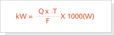
Q: Volume of the Target Space(m³)
T₁ : Initial Temperature Before Heating(℃)
T₂ : T₂: Target Temperature(℃)
△T : Temperature Difference between the Initial Temperature and the Target Temperature(T₂-T₁)
F : Insulation Factor
| Insulation Status | Insulation Factor[F] | Initial Temperature Before Heating | |||
| Excellent insulation (Sauna) | 350 | 22℃ | |||
| Very good insulation (Multi-family residential buildings) | 300 | 19℃ | |||
| Good insulation (Single-family houses) | 250 | 16℃ | |||
| Moderate insulation (South-facing offices) | 200 | 13℃ | |||
| Fair insulation (North-facing offices) | 150 | 10℃ | |||
| Poor insulation | 100 | 7℃ | |||
| Almost No Insulation | 75 | 4℃ | |||
 Outdoor air temperature is assumed to be 10℃.
Once the required capacity is estimated, the models of the panels and their numbers can be determined based on that.
Samples for the Estimation of the Capacity
| Spaces |
|
Height (m) |
Volume (m³) |
Initial Temp[T₁] (℃) |
Target Temp[T₂] (℃) |
Temp. Difference [T₂-T₁] (℃) |
Insulation Factor [F] |
Capacity (W) |
Applicable Panels | |||||
| Public bathrooms (Freeze protection) |
|
2.4 | 36 | 5 | 13 | 8 | 250 | 1,152 | S U N J O Y |
[SR-5D]*2 | ||||
| Residential bathrooms |
|
2.4 | 12 | 15 | 25 | 10 | 300 | 396 | [SR-4D]*1 | |||||
| Small-size offices |
|
2.4 | 32 | 15 | 25 | 10 | 200 | 1,584 | [SR-8D]*2 | |||||
| Patient rooms in hospitals |
|
2.4 | 64 | 12 | 25 | 13 | 250 | 3,307 | [SR-8D]*4 | |||||
| Studio apartments |
|
2.4 | 95 | 15 | 25 | 10 | 250 | 3,792 | [SR-9D]*4 | |||||
| Factory control rooms |
|
3.0 | 297 | 10 | 20 | 10 | 200 | 14,850 | S U N R A D I |
[SH-S25]*6 | ||||
| Large-size offices |
|
2.4 | 792 | 13 | 25 | 12 | 250 | 38,016 | [SH-S25]*16 | |||||
| Hair salons, Skin care shops |
|
3.0 | 248 | 15 | 25 | 10 | 250 | 9,900 | [SH-S25]*4 | |||||
| High-ceiling stores |
|
3.0 | 99 | 13 | 22 | 9 | 200 | 4,455 | [SH-S16]*3 | |||||
Location shall be determined considering the interference from finished surface of ceiling such as ventilation facility, lights or partitions.
Heater shall be installed with 600mm distance from outer wall, and between heating plates the distance shall be twice than this distance. Various size are available so that it can be installed any space.
System Design
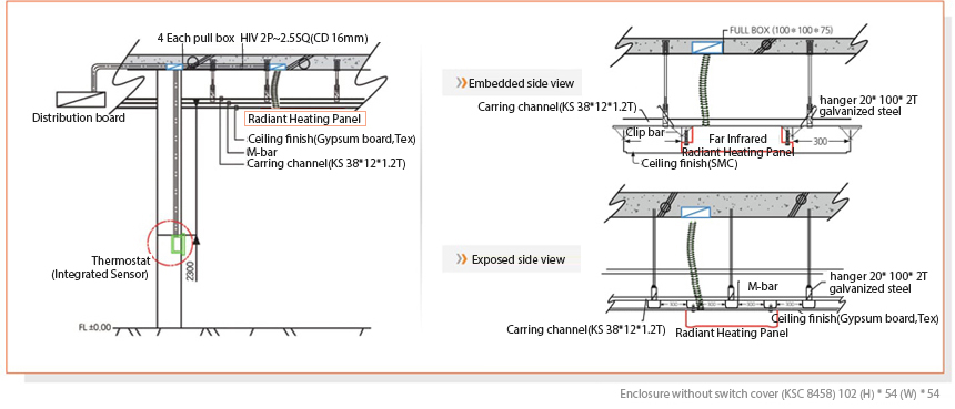
Installation Diagrams
Thermostats: Types and Circuit Diagrams
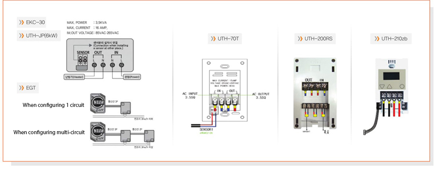
Cetral controll type Thermostat system.

Installation
Exposed type
① Select a location.
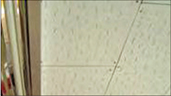
Select a location for installation considering the locations of lightings, ventilation systems, and partitions.

② Prepare 2nd power cable
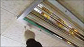
Decide where to draw the power cables on the ceiling and prepare the 2nd power cables that are connected to a thermostat.

The process sequence of connecting 2nd power cable and fixing radiant heater may be switched by site circumstances.
Embedded type
① Select a location.
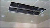
Select a location for installation and remove the ceiling tiles.
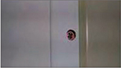
② Remove the clipbar.
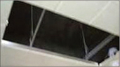
Remove the clipbar with leaving both ends by 1 cm.
③ Removed parts
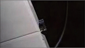
Close-up shot of an end of clipbar with 1cm leftover after it is cut
④ Connect to power cable
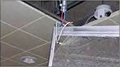
Connect the panel to the 2nd power cables that are connected to a thermostat.
Common
① Connect the power cables.
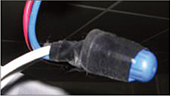
Finish the cable connections with a cap or a sleeve
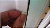
② Fasten the panel.
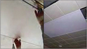
Fix the panel to ceiling structure (M-Bar or T-Bar) with fasteners through holes on the frames
③ Fastened parts
Close-up shot of a fastener
④ Insert the fastener covers.
Insert the fastener covers in the holes for more finished look.
Thermostat (In Case of EKC-30)
① Prepare a wall insert.
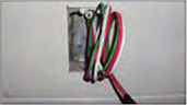
Make a wall insert for a thermostat and prepare 1st power cables that run from the distribution board to the thermostat.
② Connect the cables.
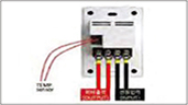
Connect the 1st power cables to input terminal and the 2nd power cables to output terminal of the thermostat. Also connect the temperature sensor, if necessary.
③ Insert the thermostat to the wall.
Install the thermostat in the wall insert, fasten it, and close it with the cover.
※ If it is hard to prepare a wall insert, you can install a thermostat in the corner of ceiling and a wall and operate it with a remote.


